4r44e rebuild manual. TAT 2019-02-20
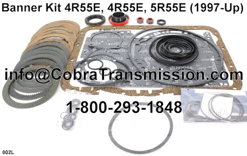
4R44E 5R55E Rebuild Kit Automatic Transmission Master Overhaul 5R44E 4R55E Ford Mercury Mazda: Oregon Performance Transmission
We supply various tips that, with practice, will help you to dismantle one in less than 20 minutes. As the valves toggle, the plugs become loose and allow fluid to pass around them. The 1 Ford Explorer enthusiast resource on the Internet since 1996. This results in no 4th in a 4R or no 2nd and 5th in the 5R unit. Place a drain pan under the assembly.
Ford Automatic Transmission Rebuild Manuals
Remove the extension housing bushing using Extension Housing Bushing Remover T77L-7697-E. The added gear is between 1st. That means going under the hood and getting to the point quickly. A repair for longevity requires tooling. It covers everything from parts identification, exploded views, home specs, wiring harness locations, routing, electrical diagrams, internal planetary components, how to disassemble a transmission, how to rebuild the individual components, torque specs, valve body identification, extension housing overviews and much, much more.
4R44E 5R55E Rebuild Kit Automatic Transmission Master Overhaul 5R44E 4R55E Ford Mercury Mazda: Oregon Performance Transmission
Use a 17mm socket to remove the five M10 x 30mm extension housing-to-transmission case screws and stud. Use a 5mm Allen wrench to remove the M6 x 20mm center support capscrew. Remove the manual valve inner lever and parking pawl actuating rod assembly. That decision is ultimately yours, as you forecast how long a marginal bore may last. The Motor Bookstore offers the best service and a 30 day money back guarantee. If you plan to rebuild, modify or enhance the performance of your Ford automatic transmission, you have come to the right store.
Sonnax Troubleshooting Tips for the 4R44E & 5R55E
The manual contains all the procedures for diagnosing and overhauling compound planetary gear sets, clutch packs and freewheel assemblies. Remove the center support retaining ring. Note: There have been many engineering changes in this transmission since its introduction. Remove the forward planetary assembly. The green side must face up.
ATSG Ford Manuals

Remove and discard the fluid pan filter assembly. This L pin falls out of position easily. If the engine stalls forward and reverse, look for blown gaskets, a worn pressure regulator bore which you can replace with and then pump or converter issues. We also cover the Ford Ranger, Explorer Sport Trac, Mercury Mountaineer, Lincoln Aviator, Mazda Navajo, Mazda Pickups, and the Aerostar. If you are looking to complete a band adjustment, torque specs, service a transmission, shift kits, or just doing a full rebuild on a unit our technical manuals are a must have. Disengage the retaining pins from the solenoid clamps. This transmission can be found in the 2005 Navigator, 2006 Explorer and Mountaineer, 2007 Expedition, 2008 F150 and 2010 Mustang.
Sonnax Troubleshooting Tips for the 4R44E & 5R55E
Your support is greatly appreciated. These locate and hold plugs, which separate and seal oil circuits. Carefully pry the transmission heat shield off of the fluid pan rail near the retaining clips. Flow will increase from an average of 1. This unit is also on the Ford Ranger and Ford Explorer. The 5R55E unit is very similar to the 4R44E, but has different computer strategy.
Ford Automatic Transmission Rebuild Manuals
Both servos are charged on the release side in reverse. Remove the overdrive ring gear, overdrive one-way clutch and overdrive center shaft assembly. Remove the torque converter using Torque Converter Handles T81P-7902-C. Note: There have been many engineering changes in this transmission since its introduction. Remove the overdrive band actuating lever shaft. Relocate the transmission to the top of a flat workbench.
4R44E/4R55E Disassembly.
Product Details Master rebuild box kit for the 4R44E, 4R55E, 5R55E, and 5R44E automatic transmissions. The Transtec gasket sets are considered a premium kit, with the better Duraprene pan gasket, and higher quality gaskets and seals throughout. Rotate transmission assembly so that the fluid pan is facing up. Remove the output shaft retaining ring from inside the case on the output shaft. The sleeves will now contain the oil circuit without end plugs, so there are few areas to leak or parts to move.
Ford 4R44E / 4R55E Transmission Rebuild Manual 1995
Rotate the transmission assembly so the converter housing is facing up. One of the major differences between the 6F35 and 6T40 applications is computer location. Use a 10mm socket to remove the four M6 x 20mm reverse servo cover screws. Remove the servo band lever and overdrive control bracket. Discard the fluid pan gasket. Valve bore wear may occur at low service use, depending on driving conditions. Remove the center support by pulling evenly around the center support web.
Ford 5R55E / 5R44E Transmission Rebuild Manual

Remove the intermediate band actuating lever shaft. This box will disappear once registered! This will loosen the pin prior to removal. This valve can be Wet Air Tested as shown in Figure 6. When this bore is worn, the solenoid oil flows around it, resulting in the loss of overdrive servo release pressure. Hydraulic controls are also different between the 6T40 and 6F35 meaning valve bodies and oil passages will not be the same. Rotate the transmission so the fluid pan surface is facing up. Install Servo Cover Compressor T95L-77028-A over the overdrive servo cover at the fluid pan rail.