Multisim 12 activation code. NI Circuit Design Suite 12.0.1 Education Edition (Multisim and Ultiboard) 2019-03-09
NI Circuit Design Suite 12.0.1 Education Edition (Multisim and Ultiboard)
Follow the instructions in the screen. Then put that on the drill press. Shape-based features typically begin with a 2D or 3D sketch of shapes such as bosses, holes, slots, etc. A strong light should be able to shine through where the tip of the drill ended. If you want to install this software for evaluation purposes, follow the link to the evaluation download located at the beginning of this document. The parametric nature of SolidWorks means that the dimensions and relations drive the geometry, not the other way around.
Ni Multisim 12.0 Crack
Screen shot captured from a SolidWorks top-down design approach. For this step you will need one middle board, the front board and 2 'sacrificial' pieces of wood they will be noticeably dented. Repeat this for as many boards as you wish, I used 2. To change it you will need to change some numbers in the arduino preferences and board definition files, as found. It would have been cool to use one solid block of would instead of 4 layers. This is because I wanted an instant startup, and it also allows for more program space although, not much.
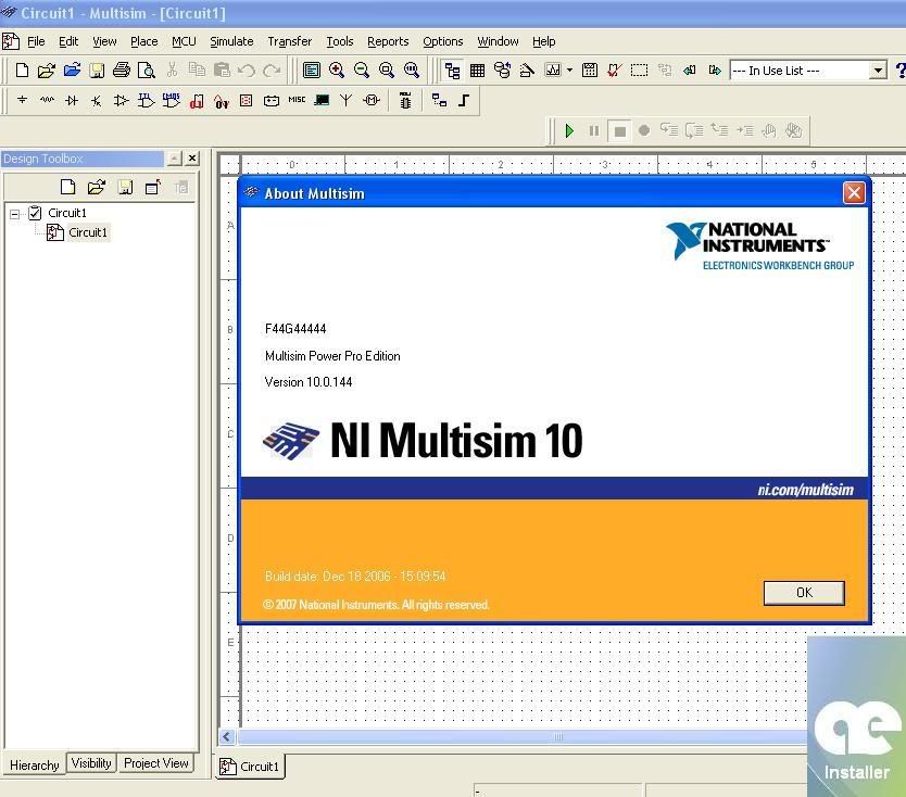
Multisim™ Full Edition
Signatures can be entered as 12355-67890. This release was created for you, eager to use Multisim 7 full and with without limitations. I loaded the program onto the atmega168 by using an to circumvent the bootloader on most chips used with Arduino. Now solder all of the rows together so there are a total of 10. I am also currently making the schematic.
NI Circuit Design Suite 12.0.1 Education Edition (Multisim and Ultiboard)

This allows the end of the jack to sit snugly in the smaller hole with the rest hidden behind the wood. The radio power is attached to the speaker pin pin 9 on arduino , so that when the alarm is sounded it turns on and automagically tunes the strongest station. Design intent is how the creator of the part wants it to respond to changes and updates. To change the flashing number, push up and down. To do this, just change the oneMin variable in the code, mine is 60116. So you end up with a box around the whole thing with no visible joining edges. It'd be soo helpful to get a more detailed shot of the breadboard + Arduino setup.
Multisim 7 Serial number
Parameters can be either numeric parameters, such as line lengths or circle diameters, or geometric parameters, such as tangent, parallel, concentric, horizontal or vertical, etc. Just as sketch relations define conditions such as tangency, parallelism, and concentricity with respect to sketch geometry, assembly mates define equivalent relations with respect to the individual parts or components, allowing the easy construction of assemblies. Finally, fasten all of the ports to the back board using hot glue on the inside. It is important to give the correct Signature Code in order to get the correct Release Code. You can also request using Service Request Manager. Next drill a larger hole from the inside of the board to within 3mm of the outer surface this depends on your jack. The controller pins analog pins 0-5 all have a 200kOhm pull-up resistor.
How do I get the product key/activation code for the student edition?
If you messed up in the last step, the wood isn't lost, use it here! To ensure this, please follow the directions below and refer to the screenshot provided. This new release brings with it a long list of quality improvements and new database parts. Hold it down for 1 second again then let up and turn the drill off. Line the bit up with a test hole and gently hold down for 1 second and let up. Screen shot captured from a SolidWorks top-down design approach. Sharing is caring and that is the only way to keep our scene, our community alive. To switch between numbers push left and right.
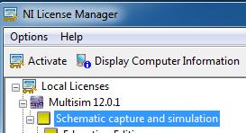
Ni License Activator 1.2

Select Next and the Activation Process. To start soldering, first bend all of the cathodes shorter leads down so they form 17 columns very close to the board, then solder them together. If you are creating your user profile, fill out the blanks and follow the instructions in the next pages. First of all congratulations for that cool project! I'll see what I can do about getting a better shot of the soldered breadboard, but at this point it is difficult to do. To return to the clock, push and hold button 1 any time. Take the miter saw and cut the ends an equal distance from the screws on either side as in the template be very careful at this point as not to poke out a hole on the saw! On the page discussing electronics setup. From what I understand, for switching on those two leds, I might have to activate the Pin1 to select green, and Pin11, Pin12 to select those two rows.
Multisim 7 Serial number

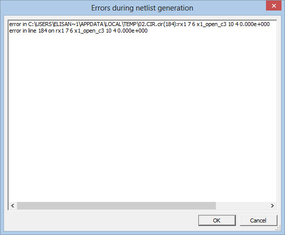
But the problem is, how do I avoid that the leds in red ovals do switch on? Step 4: Prepare the Middle Boards. Finish the activation process and Multisim will start. Operation-based features are not sketch-based, and include features such as fillets, chamfers, shells, applying draft to the faces of a part, etc. To solder the anodes together first bend all of one colour's anode up and then bend them horizontally, so there are 5 anode rows for that colour. Select Activate to start the activation process. Building a model in SolidWorks usually starts with a 2D sketch although 3D sketches are available for. Owners of purchased software after the time of release will receive 12.