Ford tractor power steering control valve. How It Works 2019-01-19
Ford/New Holland 6600 Parts

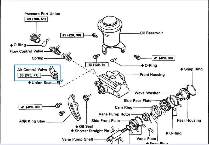
It's important to remove the top two lines first for proper drainage. The last time I was into this steering assembly was 20+ years ago. The special plungers have 'horns' on one end. The Ball Stud sets inside a pair of Ball Stud Seats which are held against the Ball Stud by pressure from the Bumper Spring. The condition of the parts you will rebuild or the core you will be sending in depends alot on how you remove the Control Valve from the car and how you disassemble it. When the Ball Stud moves off-center, it causes the Spool Valve to off-center in the Housing.
Rebuilding Power Steering Control ...
Repairing power steering on a ford 3500 industrial page 2 repairing power steering on a ford 3500 industrialfordtractorexploded diagram. Place a bucket or liquid containment device under the power steering control valve and remove the hydraulic lines using the correct sized line wrench. In this case, the Spool must be replaced. Because the pump is always in use, it can be damaged due to excessive wear, broken hydraulic lines, heat, and the natural corrosive nature of power steering. Going to get more fluid and get new cylinder hoses to valve for that right side this afternoon. Reproduction of any part of this website, including design and content, without written permission is strictly prohibited.
1975 Ford 3000 power steering control valve issues

Proper use of the is important to avoid this damage. The pictures to the right show Spools that have the ends pitted from rust. Your cylinders should have two connections facing up. Unscrewing the control valve assembly from the Centerlink without removing this pin is possible if you have a big enough pipe wrench but it will tear up the threads on the end of the Sleeve and the Centerlink. When you turn the steering wheel, the Steering Box moves the Pitman Arm which moves the Ball Stud in the Sleeve off-center. Original seats and most replacements used soft aluminum seats which seal easier against the steel tubing.
Ford Power Steering Control Valve

Right cylinder moves in opposite direction but real slow. The Centering Spring rusts, causing pitting and flaking of the hardened metal. Pull the steering arms, side caps, pull the sector shafts, remove the steering shaft, etc? If the hoses are damaged in any way, replace them as well. I also have the two plungers and two check balls. Step 2: Lift the vehicle.
control valve

The diagram I gave you above was for a 3600. Wasn't much oil in there at all but put finger down at bottom and felt the bearing in the bottom and it felt fine. This first part is not designed to scare you off from attempting your own rebuild well, maybe just a little , but to show you what you may encounter along the way. For models 340A, 340B, 345C, 345D, 445, 445A, 445C, 445D, 450, 540A, 540B, 545A, 545C, 545D, 555C, 555D, 575D, 655C, 655D, 675D, 250C, 260C. John Deere and its logos are the registered trademarks of the John Deere Corporation. The biggest problem is - you don't know what condition your parts are really in until you remove the assembly from the car, tear it down and inspect it. That is the hole where the two special plungers and two balls go.
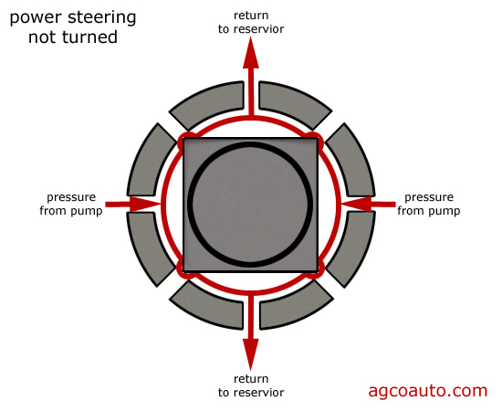
Power Steering Orbital Motor

Keep us updated but if this thread gets off the first page start a new thread as many of us won't see it. We strive to not only offer the best selection of affordably priced tractor restoration parts, but to preserve the American agricultural heritage by helping you keep your old tractors running. Join thousands of happy customers who have purchased parts and more for their antique tractor from us! Step 13: Test drive the vehicle. It should be the same amount up as down. Bleed the power steering fluid lines of any air. There was no spring between these two plungers.
Power Steering Orbital Motor

There are four lines connected to this device. Sometimes water gets past the o'ring seal under the Cap, and sometimes the water travels from the Ball Stud, all the way through the hole in the center of the Spool, into the area under the Cap. I will add more fluid tomorrow and try again. The Ball Stud is basically connected to the Spool Valve through the action of the Long Bolt, which changes tension on the Centering Spring. Step 7: Place the hoses aside and inspect them a second time. Ford 3000 parts diagram online wiring diagram ford 3000 sel tractor parts diagram car diagram images ford 3000 power steering parts diagram ford 3000 parts diagram. The drawing may show that the curved neck plunger is on the top side.
Ford/New Holland 6600 Parts
Sorry this got so long. It is a resource and a community of people who refuse to let our agricultural heritage disappear. Cannot be used with Front End Loaders. Also am replacing one of the springs in the valve one of the springs looked a little different. And many times, orders are delivered the next business day! Tractor Parts For Antique Farm Tractors Steiner Tractor Parts proudly offers a wide selection of tractor parts for vintage, old, classic farm tractors. There are several important parts inside the control valve and ball stud assembly that are not a part of a rebuild kit and these are the parts you hope to reuse. They are not tapered pipe threads.