Ford aod transmission casting numbers. How to Identify a Ford AODE Transmission 2019-03-04
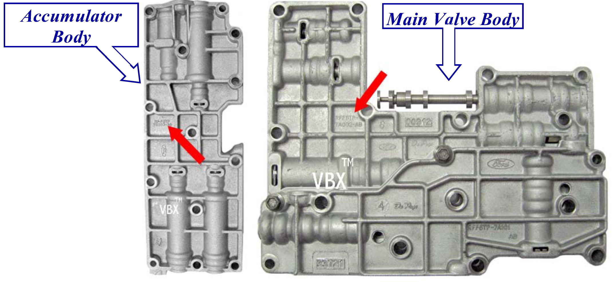
Sonnax Ford AOD, FIOD Valve Body Identification

Some seals have lips that must be angled where they seal against the piston and bore from the pressure side. Pay very close attention to the seals as you press the piston into the bore. Inspect the pressure plate for scoring and warping. It is also a unique number, and changes due to specific equipment options on a given vehicle. Line pressure was low when it needed to be high and vice versa, causing jerky operation.
4 Speed Transmission Identification
The number-5 thrust bearing goes between the sun gear and drive shell which you install next. As acceleration begins from a stop, fluid under pressure flows through the torque converter in the conventional manner via impeller, stator, and turbine. Torque the bolts to 12 to 16 ft-lbs. Cable tension is controlled at the throttle body see Chapter 9. The seal lip must be pointed toward the pressure source toward the cylinder. Check the clutch clearances; they should be. Ford Aod Transmission Identification Numbers Ford Aod Transmission Identification Numbers - You're seeking articles on our blog within the headline Ford Aod Transmission Identification Numbers of choices of articles that we got.
Ford Aod Transmission Identification Tag
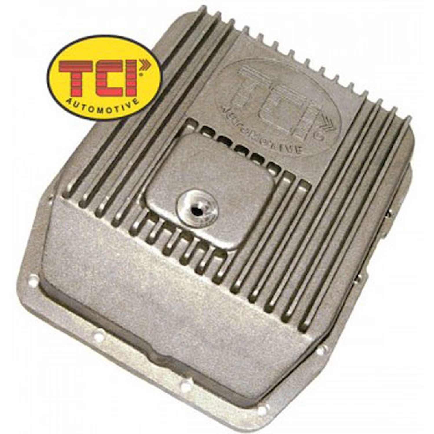
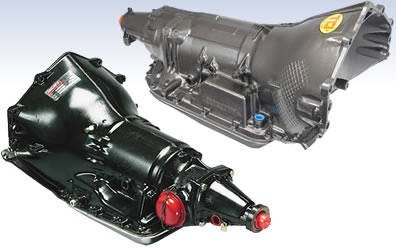
Some applications have two springs; others have one. The 2-3 shift accumulator was finally perfected by the 1989 model year and is available from a variety of transmission parts suppliers. Step 5: Fit Steel Center Support Seat the stamped-steel center support in the planet carrier and check for smooth operation against the one-way clutch. If you want more fluid capacity and better cooling, go with a finned cast-aluminum pan. At home, you can use four C-clamps from a hardware store. All of the C-series' transmissions essentially have square pans, however, the C3 has a recess on the rear passenger side, the C4 has a bulge on the front passenger side corner, while the C6 has a recess on the rear passenger side that faces the rear of the vehicle. Step 8: Install Intermediate Clutch Piston Perform the intermediate clutch piston installation with great care to protect the inner and outer seals.
Ford AOD Transmission Assembly Guide
The key to success with Glyptal is good paint adhesion, which means you must have a clean surface before application. According to the parts book, this switch fits a 1968 Ford Thunderbird with tilt steering wheel. This kit consists of the booster valve and a sleeve that eliminates the sticking pressure regulator boost valve problem and resulting failure. Step 8: Install Direct Clutch Steels and Frictions The direct clutch discs and plates drop in alternately. The bolts should be torqued to 16 to 20 ft-lbs in a crisscross fashion.
How to Identify Ford Automatic Transmissions

Hard parts are rugged and can typically survive several overhauls. Proper clutch piston seal installation is crucial. You should also use a Kevlar-faced 2-inch overdrive band for extreme-duty service. Assembling clutch packs and other subassemblies requires the detail of neurosurgery because it is so easy to make a mistake when installing seals, snap rings, and clutches. Torque bolts in a crisscross pattern to 16 to 20 ft-lbs. Again, everything must have generous amounts of lubrication.
Sonnax Ford AOD, FIOD Valve Body Identification

Rough surfaces should be dressed until smooth and serviceable. Intermediate Internal Assembly Step 1: Install Sun Gear and Thrust Bearings Fit the sun gear into the planet gears, which can be tricky. Step 10: Install Pump Sealing Rings Carefully install the iron pump seal rings. Do the same with clutch discs after you saturate them in fluid. Other types of installation tools are available. The manual valve has detents to keep it in the selected gear range. A small filtering screen should always be included.
How to Identify a Ford AODE Transmission
It is a true 4-speed automatic overdrive transmission. This could mean revisions to the part or multiple manufacturers supplying the part to Ford. Step 8: Assemble Reverse and Forward Clutches Stack the reverse clutch drum on top of the forward clutch and input shaft. Install the number-7 through number-10 output shaft sealing rings. Brian makes sure he has clean parts and plenty of transmission assembly lube and fluid on hand before starting. Step 2: Check Intermediate Clutch Depth Precision Measurement When you get to the last intermediate steel plate, check clearances with a depth micrometer.
Ford Aod Transmission Identification Tag
Other information indicates it was an Engine Engineering Division design, weighs 9 pounds, provides information on the quality control inspection, and the date packed. Seal contact surfaces should be true and free from scoring. Position the depth micrometer at the pump to the transmission face and take the measurement from there to the clutch plate. Step 2: Install Pump Gasket Lay a thin film of transmission assembly lube on the pump gasket and transmission mating surface. Make sure you have lubed everything for smooth assembly and function. The cam pushes the parking pawl into the rear gear, locking the output shaft. They wear at different rates, which is why thickness can vary.
Ford Aod Transmission Identification Tag

Both became wider on later models to better handle the load. Alternately lay the clutches and plates until the last steel. Valve body installation mandates the utmost care with proper bolt placement. Identify transmission, transmission lookup, The staff has been amazing to work with and takes care of their customers better than any other company i have ever dealt with. Coat the gear teeth and bearing with assembly lube and work the sun gear back and forth. Make sure the servo actuating rod is seated in the overdrive band.
Ford AOD Transmission Assembly Guide
Step 3: Install Low-Reverse Servo Cover Use a snap ring to install the low-reverse servo cover. The seal should be packed with assembly lube to prevent lip spring loss. Date codes are located in various areas, and are normally comprised of 3 or 4 digits. Position the throttle valve return spring as shown. Always use an assembly lubricant that works with transmission fluid.