92 ford ranger 4x4 fuse. 1983 2019-04-03
Ford Ranger (1998)
The ohmmeter should indicate a low resistance value less than 50 ohms while the switch is being depressed. Sitting in a drive thru, we started playing with the 4wd switch cause it wasn't lighting up 93 Exploder, old push button style but we kept hearing a relay or soloniod snapping in the back of the Exploder, which brings up a point, is it possible the relay could be shot and sending the wrong amount of power to the motor??? First, open your door, open up the drivers side jump seat, and check the black box in there. The ohmmeter should indicate a low resistance value less than 50 ohms while the switch is being depressed. In either of these instances b or c power and ground should be verified before scrapping a 4x4 module. Attached are the schematics of your control system if that helps.
FORD Ranger

. I have a haynes manual for the truck and they dont list a diagram either. There are two fuse boxes on the Ford Ranger: one is located under the hood, while the other is found underneath the driver side dashboard. If not, ensure that the volt meter has a good ground and try again. Disconnect the wiring harness to the truck first though. Refer to the following chart for the appropriate ohmmeter readings in each transfer case position. To verify issue 1, see part d-I in step 5.
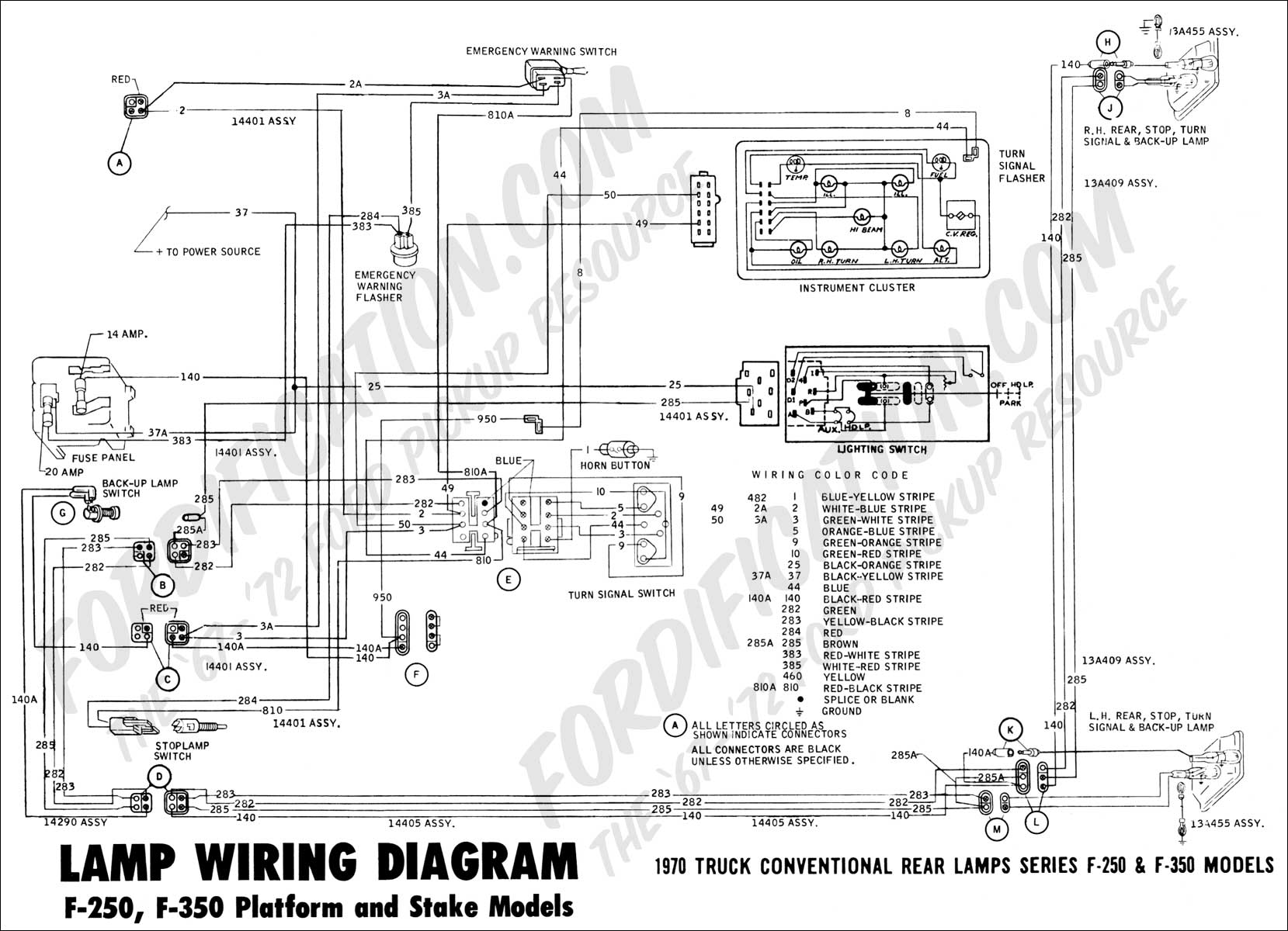
92 Ford Ranger Engine Wiring Diagram • Auto Wiring Diagram
Try to replace the fuse, and see what happens. The Exploder I'll do on my own time as well. Check to make sure all fuses for the system are good. Under the hood the main 60 amp fuse was blown. If you read that write up they tell you what wires go to the motor and you can try driving the motor directly with 12 volts to see what happens. By the way, thanks everyone for your help! A blown fuse for the motor power circuit, or similar problem would also cause those symptoms. Are there relays for the motor and such in any other place other than the main fuse panels? Replaced the fuse, and as soon as the key was turned the fuse blew again.
Need 92 ford ranger interior fuse box diagram

The next step will check the circuitry to the shift motor. Mar 29, 2017 Keith, 1995 ford ranger, looks like interior light fuse is 27, 10 amp. But I appreciate your assistance, regardless. So its possible also that the xfer case is so 'dead' that it physically cannot engage and that is causing the whole 4x4 problem to begin with. The next step is to verify that the module is supplying voltage to the shift motor.
Ford Ranger (1983

If you have 12 volts there, your module is sending a 12 volt supply to the 4x4 switch. A simple trick that lets you troubleshoot without wasting a lot of fuses is to make a pair of wires you can plug into the fuse socket then connect them to a 12 volt light bulb. The motor does not engage and nothing does anything with either module plugged in. Just open up the drivers side jump seat and you'll see it. This circut allows elec windows, 4 x 4 elec engage. This box will disappear once registered! I suppose I should have been more clear - I was referring to the fuse box located under the dash, whereas the diagram you provided is of the one located inside the engine compartment don't ask me why the truck has two. If these tests result in transfer case problems, then the case itself is the problem.
1983

If a problem occurs with a light, door lock switch or piece of audio, this is the first place to inspect. Again, if this occurs, the 4 low switch is good. A good place to look for your problem is the wiring harness between the door hinges. You might still have a good motor. If it lights up and stays on, it indicates that the module is likely bad. The shift motor is fine; I hot wired it and it works fine, it just doesn't work via the normal cab control switch as it should.
4x4 not engaging, and no light

According to the Haynes manual, that fuse controls the charging system. The photo above shows one mounted under the jumpseat on the drivers side of an extended cab. The interior lights do not work and all the lamps look good. I have them on mine. With the key off, reconnect the two connectors. Hard to say if that's just one relay or both. The fuse box located in the engine compartment houses the fuses for the mechanical parts of the motor.
Interior Fuse Box Location: 1993

If any of these tests fail, you will have to check the wires from the module to the back of the switch for continuity. You are essentially checking for voltage at this pin to ensure that it is getting voltage, and that the connector is good. The bulb will limit current to a safe value and will give you a visual indication of when the short circuit in present in the circuit. The ohmmeter should indicate a low resistance less than 50 ohms while the clutch pedal is being depressed. There are two fuses that supply power to your 4x4 shift system — one located under the hood, the other under the dash. The whole diagram was too big.
92 Ford Ranger Engine Wiring Diagram • Auto Wiring Diagram

This wonderful picture collections about 92 ford ranger engine wiring diagram is available to download. With all connectors plugged into the module, back probe the dark blue wire terminal 2 on the 5 pin gray connector — the one on the lower right side of the module. As a matter of fact you canprobably hear it if you don't have the engine running. Connect an ohmmeter between terminals 2 light green and 3 light blue. This article is going to cover the electrical shifting system, and will not touch on your 4x4 hubs and how to fix them. If these tests result in transfer case problems, then the case itself is the problem.
Need 92 ford ranger interior fuse box diagram

Up to now, the following should have been verified: a. If you know how to use a volt meter, you should know how to find a short in the circuit, and will need a wiring diagram to do so. And I didn't even blow the fuse! This module will have three connectors going to it — one will be a pig tail, the other two will be located on the right side of it side towards the front of the truck. We collect this best picture from online and choose the top for you. The speed sensor picks up the rotating speed of the transfer case rear output shaft from two notches that are cut in opposite sides of the outer ring of the clutch housing.