2006 honda cbr600rr repair manual. Honda CBR600RR Repair Shop Manual 2003 2019-05-07
2006 HONDA CBR600RR MOTORCYCLE SERVICE REPAIR MANUAL DOWNLOAD

If the stator coil windings are in good condition the three readings should be within range shown in the Specifications at the start of this Chapter, and there should be no continuity between any of the terminals and ground. Note: Before condemning the stator coils, check the fault is not due to damaged wiring between the connector and the coils. If the gear appears stuck, rotate it clockwise as you withdraw it to free it from the starter clutch. Doing so damages the adjuster screw and requires shock absorber replacement. This is the same manual your Bike Repair shop uses to repair and diagnose your bike!!! A properly stored vehicle is much easier to return to service. Install the new assembly in a reverse sequence. If it doesn't, the starter clutch should be dismantled for further investigation.
Honda CBR600RR Sportbike Repair Manual 2003
The Official Honda manual just gives you the facts, the Cyclepedia manual however tells you tips to do it right. To remove the sprag assembly release the circlip that holds it and note which way round it fits. Covers the entire vehicle from front to back, its the same type of Manual that is used by Professional Mechanics to service or repair your motorcycle. This is especially true in areas of extreme temperature variations. I like the instructions with a picture.
Honda CBR 600 RR 2003

Turn the rebound adjuster screw with a screwdriver. Consider the following list the minimum requirement. No shipping fees, no waiting, no hassle. If you do not have an auxiliary stand it is best to drain the oil. We will be happy to assist you in a prompt manner. Check the needle roller bearing and the bearing surfaces on the starter driven gear hub and the starter clutch housing boss.
Honda CBR600RR Motorcycle (2003

It should be insulated to minimize extreme temperature variations. This deterioration can be minimized with careful preparation for storage. This is the full hard position. Exhaust System — Exhaust Pipes, Muffler Engine — Cylinder Head Cover Removal, Camshaft Removal, Camshaft Installation, Cylinder Head Cover Installation, Stator Coil and Flywheel, Clutch, Right Side Engine Components, Oil Cooler, Engine Removal, Oil Pan, Cylinder Head, Crankcase Splitting, Crankshaft and Connecting Rods, Pistons and Cylinders, Transmission, Crankcase Assembly, Engine Installation Final Drive — Chain, Engine Sprocket, Rear Sprocket Front Brakes — Pad Replacement, Brake Calipers, Master Cylinder Rear Brakes — Pad Replacement, Brake Caliper, Master Cylinder Wheels — Wheel Bearing Replacement, Front Wheel Removal, Front Wheel Installation, Rear Wheel Removal, Rear Wheel Installation Front Suspension — Fork Settings, Fork Disassembly, Fork Seal Replacement, Fork Inspection, Fork Reassembly, Fork Removal and Installation Steering — Steering Removal, Bearing Replacement, Steering Installation Rear Suspension — Settings, Shock Absorber, Swing Arm, Suspension Linkage Electrical System — Electrical Specifications, Battery, Charging System, Ignition System, Starter Motor, Head Light, Tail Light, Position Light, Fuel Level Sensor, Meter Assembly, Switches. The perfect tool can now be used in a mobile environment. If you have an auxiliary stand, place the bike on it so that it is level - this minimizes oil loss.
Honda CBR600RR Sportbike Repair Manual 2003

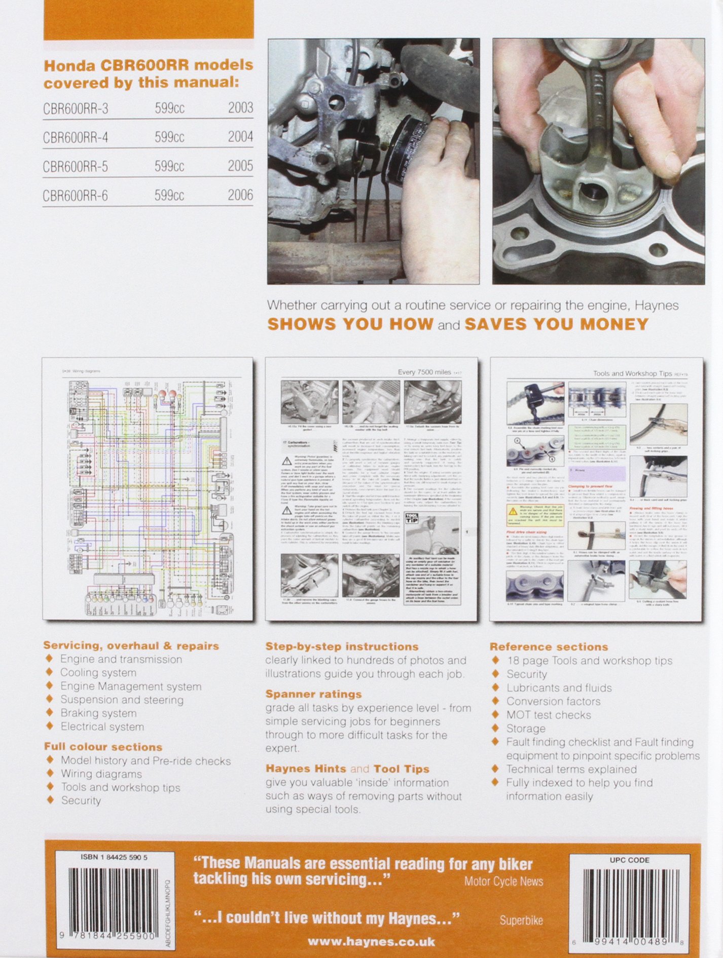
This Service Repair Manual also contains illustrations, diagrams, specifications, step by step instructions, pictures, procedures and much more. The photos you see here are actual photos from the manual. The factory service manual is much dryer and harder to follow by comparison. The high level of detail, along with hundreds of photos and illustrations, guide the reader through each service and repair procedure. Do-it-yourselfers will find this service and repair manual more comprehensive than the factory manual, making it an indispensable part of your tool box.
Honda Motor Manuals Download: Honda CBR600RR 2003
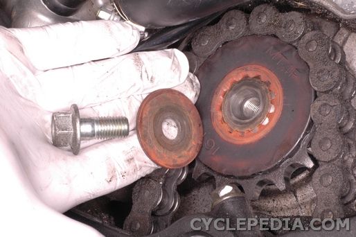
Check the connector terminals for corrosion and security. Secure the sprag assembly with the circlip. Avoid areas close to saltwater. Measure the outside diameter of the hub and check that it has not worn beyond the service limit specified. Check with an insurer regarding coverage while in storage. The access is working fine.
Honda CBR600RR Motorcycle (2003
Using this repair manual is an inexpensive way to keep you vehicle working properly. If not, the alternator stator coil assembly is at fault and should be replaced with a new one. All repair procedures are covered. The rear shock absorber is equipped with a rebound damping adjuster on the bottom right side of the shock housing B, Figure 20. Clymer manuals are copyright protected. Some other manuals lack specific instructions.
Honda CBR600RR 2003

This highly detailed Digital Repair Manual contains everything you will ever need to repair, maintain, rebuild, refurbish or restore your vehicle. These manuals are specifically written for the do-it-yourselfer as well as the experienced mechanic. Keep it up, they work great. The Clymer online manual is excellent for viewing on tablets such as the iPad. A heated area is best, but not necessary.
2006 Honda Cbr600rr Workshop Service Repair Manual
If the bearing surfaces show signs of excessive wear or the bearing itself is worn or damaged, they should be replaced with new ones. Simple to complicated repairs can be completed effortlessly with the information provided. Tons of pictures and diagrams at your fingertips!! Your one year subscription purchase is added to your MyClymer Toolbox and can be accessed wherever you have internet service with your account information. Apply clean engine oil to the sprags. Buy Now and receive immediate access to this manual! Our manuals are fully funtional, meaning the pages are easily found by category, and each page is expandable for great detail! The rebound adjuster is not set at its standard position. . From there you can view and print the whole thing, or only the category, or page you need! Highly detailed repair manual with complete instructions and illustrations, wiring schematics and diagrams to completely service and repair your vehicle.