1999 isuzu pickup manual. Isuzu Pickup Manual for Sale 2019-01-11
1994 Isuzu Pickup Auto Repair Manual

Go to Step 11 Was a problem found? They change them from time to time to keep it interesting and if you happen to own one of the sample vehicles, then you just scored free unlimited access until they change it again. Condition Possible cause Correction Turn Signal Will Not Stay In Turn Foreign material or loose parts Repair or replace signal switch. Pack the four grease cavities of the spider with a high scratches may not exceed 0. Torque: 20 N·m 14 lb ft f Adjust surfaces of the cylinder block and the oil pan support. The master cylinder is not repairable.
ISUZU 1999 RODEO WORKSHOP MANUAL Pdf Download.

Lay the shaft horizontally on a bench and secure. Install transmission mounting fixing bolts and nuts to 23. If roughness results,replace Was a problem corrected? Refer to Restricted Exhaust System Check. Use bearing remover J—42379 and pilot 14. When installing the steering column cover, be sure to 7. Strategy—Based Diagnostics Most Scan Tools, such as the Tech 2, have The strategy—based diagnostic is a uniform approach to.
REPAIR MANUAL FITS 1981

Be sure to discard used O-ring. Remove dust boot; guide bolt and lock bolt. Disconnect the battery ground cable. Refer to Bleeding the Power Fluid Level Steering System in this section. Move drive belt tensioner to loose side using wrench then remove drive belt. The probe must positions — turn the crankshaft further at the be set precisely between the notch marks, square to fastening bolt of the timing belt drive gear by 45°. Torque: 103 N·m 76 lb ft f Place hub on a wood workbench or a block of wood approx.
Isuzu Pickup Manual for Sale

Shimmy, Shake or Vibration Tire or wheel out of balance. Install roter and vanes to cam. The Isuzu Pickup was also pretty reliable. We do it ourselves to help you do-it-yourself, and whatever your mechanical ability, the practical step-by-step explanations, linked to over 900 photos, will help you get the job done right. Tap bearing only hard enough to break assembly away from snap ring.
1994 Isuzu Pickup Auto Repair Manual

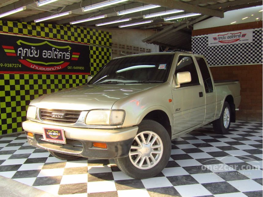
Please see the shipping and payments tab for delivery window. Start and idle the engine. The gasoline engine serial number is stamped on the left rear lower area of the cylinder block above the starter. Install torsion bar arm bracket and tighten it to the specified torque. Install ball bearing 17 , using a bench press. Inflate tires to recommended pressure. The steering was pretty accurate, but it needed small adjustments at higher speeds.
Isuzu
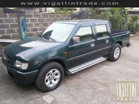
Do not let calipers hang from the vehicle by the brake line or hose. Install the insulator on the coil spring. Remove transfer protector 6 and fairing plate 7. Use a check sheet or other method to identify the circuit or electrical system component. Assemble clutch pack unloading tool. Remove the brake caliper fixing bolt and hang the caliper. There were two generations of this vehicle and they still remain popular today.
1994 Isuzu Pickup Auto Repair Manual

When installing the heater unit, defroster nozzle and noting the following points: center vent duct, be sure that the proper seal is made, 1. Armature Brush Holder Check for continuity between commutator and segment. The sensor is attached Speed Sensors, Warning Light, and G-sensor. Oxygen sensor heaters are required by the Primary System—Based Diagnostics. Note: Mouseover the icons to see a screen shot thumbnail, click to enlarge. Disconnect coil integrated module connector.
Free Isuzu Repair Service Manuals
Install lock bolt and guide bolt 8 and tighten the bolt 2. When boot clamps becomes loose, remove by hand. The engine makes sharp metallic knocks that change with throttle opening. Water in fuel system Clean Fuel filter clogged Replace filter. If the conditions for the test as described above are 8. Ping, Snap, or Click in Drive Line Loose bushing bolts on the rear Tighten the bolts to specified torque. Worn upper or lower control arm Replace.
Print & Online Isuzu Car Repair Manuals
The order in which they. Run the engine until the power steering fluid reaches 5. Remove crankshaft pulse pickup sensor disc. If the misfire is random, check for the following conditions: f System grounds —. Remove the engine hood opening lever, then remove instrument panel lower cover. Inflate tires to proper pressure. Use the companion flange holder J—8614—11 to install a new end nut 2 and tighten to the specified torque.
Isuzu Pickup Manual for Sale

Pull out the mode door while raising up the catch of door lever. If misfire follows the coil, replace the ignition coil. Remove upper inner return spring 9. Bearings f Bearings visually and by feel. Place a new snap ring internal in inner shaft. Select the shim using chart; Pinion marking Dial —1 —2 —3 —4 —5 —6 —7 indicator reading Inches 0. Install fuel rail assembly to intake manifold and connect hose between fuel pressure regulator and throttle body.