1990 isuzu trooper wiring diagram. Isuzu Trooper Questions including make a 1990 Isuzu Trooper shift from first to 2019-02-04
fuse map

Tighten the bolts in diagonal sequence as illustrated. Remove the cross pin, using a soft metal rod and a 5. Remove torsion bar, refer Torsion Replacement in this section. Raise the vehicle and support the frame with suitable safety stands. First, check that your problem really is the pump. Engine coolant temperature is low. Loosen the inflator module fixing bolt from behind the 10.
ISUZU TROOPER 1999 WORKSHOP MANUAL Pdf Download.
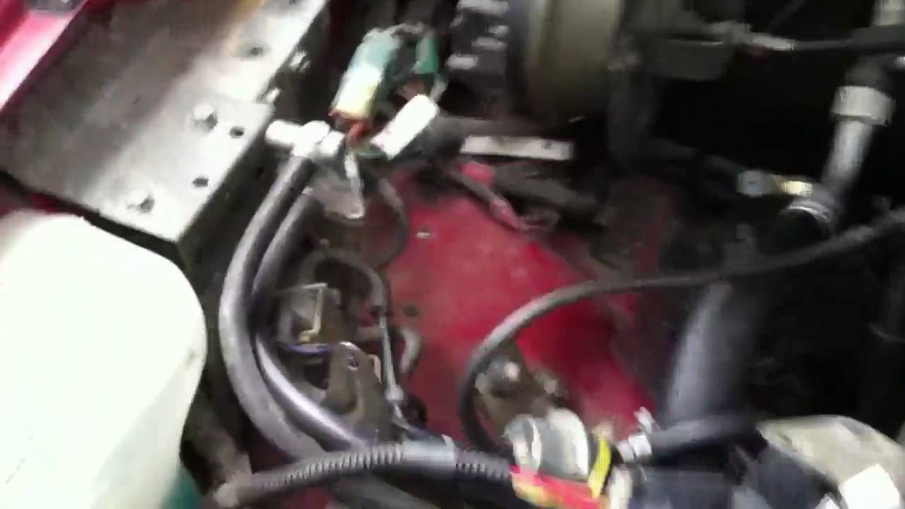
Raise the vehicle and support the frame with suitable damage, corrosion or any other abnormal conditions are safety stands. Select the shim thickness using the chart; Pinion marking —1 —2 —3 Dial indicator reading Inches Inches Inches Inches Inches Inches Inches Inches 0. The automotive wiring harness in a 1990 Isuzu Trooper is becoming increasing more complicated and more difficult to identify due to the installation of more advanced automotive electrical wiring. Raise the vehicle and support the frame with suitable safety stands. Adjust the control lever assembly cables. Should the four injectors be reconnected simply according to position in the wiring harness or should the injectors be colored in the same order? Support the inflator module and carefully connect the module connector.
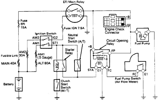
1990 Isuzu Trooper and Trooper II Electrical Troubleshooting Manual

The center line of the pinion gear is below the center line The axle shafts are supported at the wheel end of the of the ring gear hypoid drive. Remove stabilizer bar bolt and nut and push the Installation stabilizer bar aside, then remove the relay lever bolts 1. The fourth reason is that you can always get in contact with me any concerns or questions. Tighten the bolt to the specified torque. Install nut and tighten it to the specified torque. You might be a technician that wishes to try to find referrals or resolve existing troubles. Why should download this manual? Remove the shock absorber lower end from the lower control arm.
Isuzu Trooper Questions including make a 1990 Isuzu Trooper shift from first to

Install bracket and tighten to the specified torque. Remove antilock brake system speed sensor fixing brackets 2 attached to the frame and center link. If you want to know more or withdraw your consent to all or some of the cookies, please refer to the. Remove the inner bearing outer race 1 and the outer rod and a hammer. Diagrams 9761403: Isuzu Npr Rear Light Wiring Diagram — Isuzu, size: 800 x 600 px, source: coolspaper. .
ISUZU TROOPER 1999 WORKSHOP MANUAL Pdf Download.

Discharge and recover refrigerant f Refer to Refrigerant Recovery in this section. Condition Possible cause Correction Turn Signal Will Not Stay In Turn Foreign material or loose parts Repair or replace signal switch. Retighten to the bolt and nut specified torque after the 1. Apply a thin coat of power steering fluid to the new seal ring 1 and be sure to discard used part, then install seal ring. Once you have loosened the nut the. Apply setting marks 1 to ensure reassembly of the parts in their original position, then remove outer rod 1.
Can You Email Me a Diagram for the Entire Injector Harness?

If you go to my isuzu parts besure to notice the tabs at the top of each diagram --they will tell you if the diagram is for a 4 cyl, a deisel or the v6. Looking for info concerning Isuzu Npr Wiring Diagrams? The ring gear should always be replaced with the 2. Always verify all wires, wire colors and diagrams before applying any information found here to your 1990 Isuzu Trooper. Go to Step 2 harness. Description Isuzu Trooper 1990 System Wiring Diagram is the perfect solution for you, at a great price, and including many useful information for all technicians, electrical system, schematics, in fact is suitable for everyone who wants to repair, learn, work in the field of car repairs.
Isuzu Trooper Repair Manual

Attach the compressor to the J-34992 holding fixture and mount the compressor in a vise so that the compressor will be in a horizontal position and the shaft can be turned with a wrench. The number indicates a necessary change in the pinion mounting distance. Remove rear nut and washer. The only way to add fluid or check the fluid level of the transmission is through the fill plug in the transmission pan. Plus, it provides repair procedures with detailed specifications and photographs. It must Sheared Injected Plastic Pin be within 1 mm 0.
1990 Isuzu Trooper Remote Starter Wiring Chart

Remove the pump return line at the pump inlet and plug the connection on the pump. Raise the vehicle and support it at the frame. Be sure to install the sensor and the insulator on the 8. Fix the parking brake cable mounting bolt Behind the 11. Install the dial Legend indicator with the discs and arbor. Using punch J—39209, stake the flange nut at two 2. Inspection and Repair Torque: 103 N·m 76 lb ft Make necessary parts replacement if wear, damage, 4.
Isuzu Trooper Repair Manual
Worn upper or lower control arm Replace. Remove the parking brake cable from the trailing link. Torque: 177N·m 130lb ft 9. Automotive wiring in a 1990 Isuzu Trooper vehicles are becoming increasing more difficult to identify due to the installation of more advanced factory oem electronics. Lead is usually caused by: 1. I got 2 very good responses to my question a few days ago concerning the Injector Wiring.