09g valve body wiring diagram. 01m Valve Body Diagram 2019-03-02
Skoda Gearbox 09G Workshop Manual (Edition 07.2014)
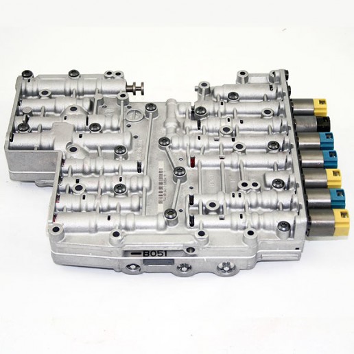
And we also think you came here were looking for this info, are not You? Obviously, the generally valid basic safety rules apply to repair work. It is a Five Speed transmission equipped with Three Driving Clutches, Four Holding Brakes and Three freewheels. This Knowledge about 01m transmission valve body solenoid diagram has been submitted by Maria Nieto in this category section. The removal and installation procedure is only possible together with the gearshift mechanism. It also includes a complete exploded view of the valve body and identification of all valves and springs.
01m Valve Body Diagram
We never store the image file in our host. It also includes a complete exploded view of the valve body and identification of all valves and springs. From several choices on the web were sure this image might be a perfect guide for you, and we sincerely hope you are satisfied with what we present. It is easy, you should use the save button or place your cursor to the picture and right click then choose save as. As a result, the number of friction plates, and planetary gears 3 or 4 pinion , will vary depending on torque load requirements of the specific vehicle. How to acquire this 01m valve body diagram image? We are very grateful if you leave a opinion or feedback about this 01m valve body diagram post.
TF

This Transmission features a Torque Converter with Lock-up Clutch, 3 driving clutches referred to as clutch A, B and E, 2 brake clutches referred to as clutch C and D, a Lepelletier Planetary Gear Train, and internal Transmission Control module referred to as a Mechatronic Module. It also covers passage identification of the case, valve body and spacer plate. The plug connection -5- is directly placed onto the multi-function switch. They apply to this workshop manual. The manufacturer does not publish any information about this valve body. This Transmission features a Torque Converter with Lock-up Clutch, 3 driving clutches referred to as clutch A, B and E, 2 brake clutches referred to as clutch C and D, a Lepelletier Planetary Gear Train, and internal Transmission Control module referred to as a Mechatronic Module.
VW

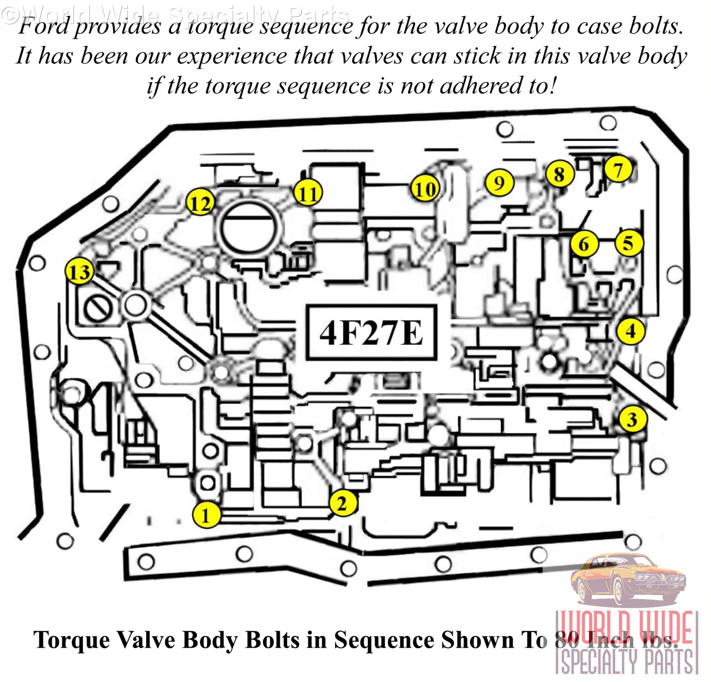
It also includes a complete exploded view of the valve body and identification of all valves and springs. Skoda Gearbox 09G Workshop Manual Edition 07. This addition confines clutch to clutch shifting without any sprag assist between 5th and 6th speeds only. You can also find other images like wiring diagram, parts diagram, replacement parts, electrical diagram, repair manuals, engine diagram, engine scheme, wiring harness, fuse box, vacuum diagram, timing belt, timing chain, brakes diagram, transmission diagram, and engine problems. The following pages provide information on the valve body breakdown including check ball function and valve function for this family of transmissions. The basics for this Self-Study Programme are covered in the multimedia training course 'Power Transmission 2' and in the previously published self-study programmes on multi-step automatic gearboxes.
Skoda Gearbox 09G Workshop Manual (Edition 07.2014)

These inputs control the main characteristics of how this transmission operates. The Tiptronic switch -F189- is installed firmly in the gearshift mechanism and cannot be replaced individually. . This Manual Covers Aspects Below: Component Application Chart. This is a Must have if working on these models! The solenoid is installed firmly in the gearshift mechanism and cannot be replaced individually. The following pages provide information on the valve body breakdown including check ball function and valve function for this family of transmissions. You can also find other images like wiring diagram, parts diagram, replacement parts, electrical diagram, repair manuals, engine diagram, engine scheme, wiring harness, fuse box, vacuum diagram, timing belt, timing chain, brakes diagram, transmission diagram, and engine problems.
Skoda Workshop Manuals > Octavia Mk2 > Power transmission > Gearbox 09G > Automatic gearbox, control, assembly, housing > Electric/Electronic components and fitting locations > Electric/electronic components and fitting locations (Octavia II, Superb II)
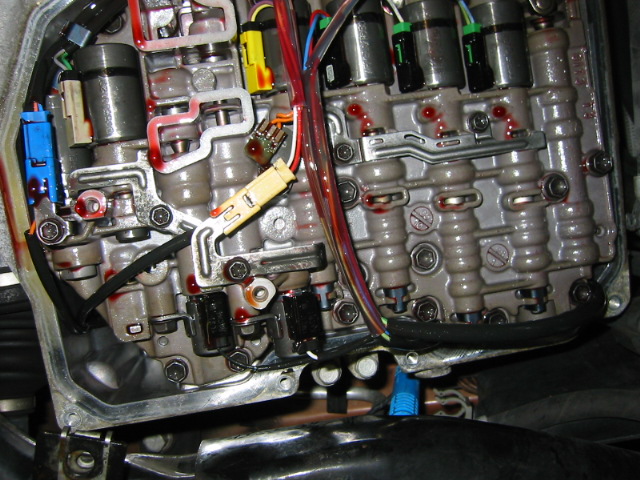
The following information shows operational strategy of what gears are available in what range and also provides detailed information on Valve Body Breakdown, theory of operation and component location and Identification. In other words, the computer for the transmission is mounted onto the valve body and is submerged in transmission fluid. That is why we are presenting this content at the moment. Now includes 1998-up supplement pack. Switch for Tiptronic -F189- Fitting location: The Tiptronic switch -F189- is integrated in the printed circuit board -B- of the gearshift mechanism.
01m Transmission Valve Body Solenoid Diagram
We know every persons opinion; will be different from one another. It also includes a complete exploded view of the valve body and identification of all valves and springs. It is an enhanced A750E used in various Toyota models. Selector lever position indicator -Y6- Fitting location: Integrated in the dash panel insert. This arrangement makes six forward speeds and reverse possible, with only five clutch packs and one freewheel. This arrangement makes six forward speeds and reverse possible, with only five clutch packs and one freewheel. It was widely used throughout the world except here in the United States at the time of printing.
Skoda Gearbox 09G Workshop Manual (Edition 07.2014)

In other words, the computer for the transmission is mounted onto the valve body and is submerged in transmission fluid. In addition, the normal basic safety precautions for working on motor vehicles must, as a matter of course, be observed. The 09D transmission uses a Lepelletier arrangement, using a simple planetary coupled with a Ravigneaux type, dual planetary. The 09D transmission uses a Lepelletier arrangement, using a simple planetary coupled with a Ravigneaux type, dual planetary. It also includes a complete exploded view of the valve body and identification of all valves and springs. Similarly to this image, within our opinion, this is one of the greatest photo, now what is your opinion? We just links any topics about A4cf2 Transmission Valve Body to many other sites out there. In no way does Wiring Diagram Pictures claim ownership or responsibility for such items, and you should seek legal consent for any use of such materials from its owner.